[32+] Pin Wiring Diagram Of Dol Starter, DOL Starter Connection And Wiring Diagram With OLR
It is used in the components of the Dol starter to protect the circuit against any kind of overcurrent. It helps to ensure the safe functioning of the circuit and also prevents any damage to the components due to excessive current. 3. Operation of Dol starter: 3.1 Wiring diagram:

Dol Starter Circuit Wiring Diagram Dol Starter Wiring Diagram Start Direct Motors Engineering
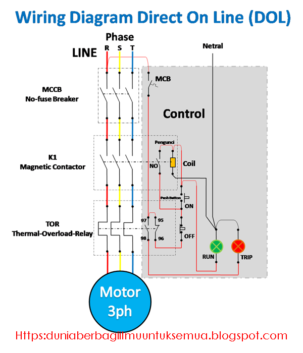
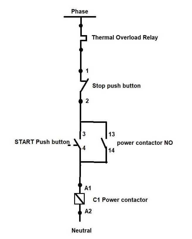
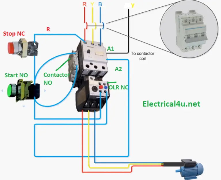
DOL starter control circuit consists of a start push button generally green, a stop push button red, a power contactor, a bimetallic overload relay, and indication lamps. The control circuit wiring diagram is shown in the below diagram. When the start button is pressed it energized the contactor coil and contactor contacts get latched hence.
Rangkaian DOL (Direct On Line) Starter Motor 3 Ph, Wiring diagram dan penjelasan lengkap VOLTECHNO
Electricians Matt and Joe look at the wiring and connection in a 3 phase direct online started (DOL). In this video we explains how to connect the supply and.
DOL StarterWorking, Control Circuit Wiring Diagram Electricalsblog
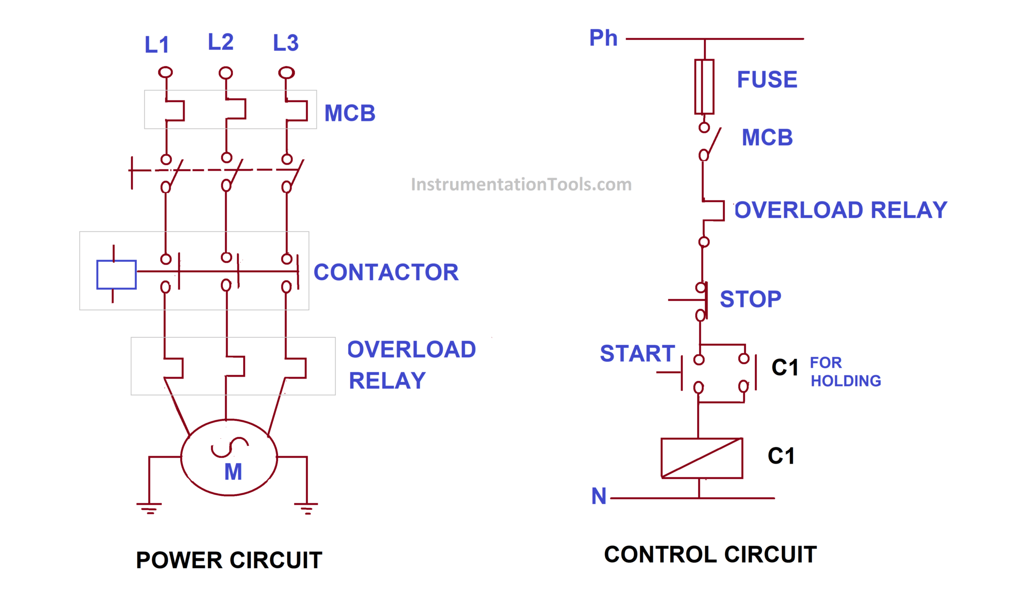
DOL Starter Circuit Diagram DOL Starter Working Principle. The DOL Starter is started by simply pressing the Start Push button and stopped by pressing Stop push button. This method has easy way of controlling the device. If the push button is pressed, the contactor gets energised and gets closed. Even after the push button release also the.
Wiring Diagram For Direct On Line Motor Starter Wiring Diagram and Schematic Role
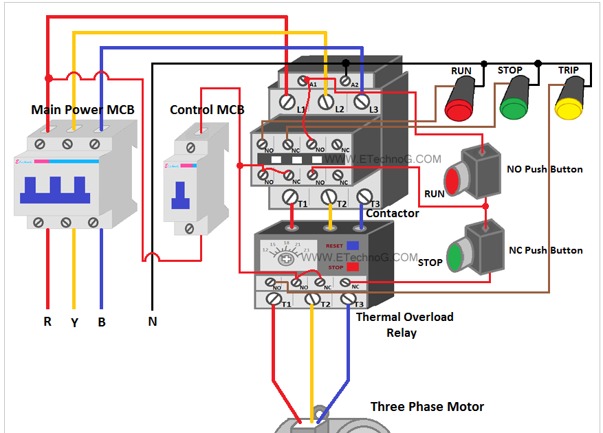
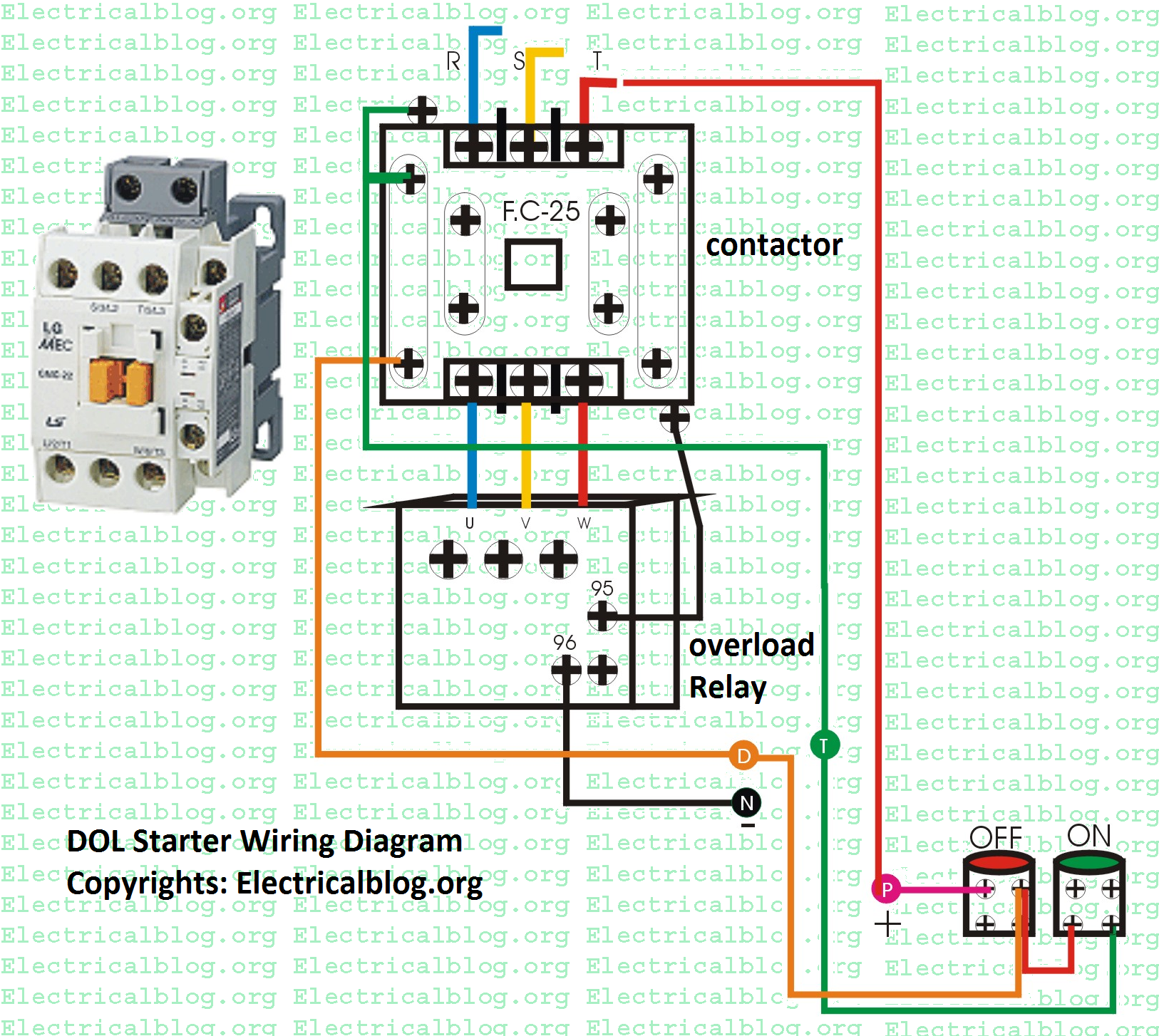
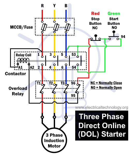
In the above three phase dol starter wiring diagram. All connection i shown with complete guide. The 3 phase incoming supply shown (L1, L2, L3). The three phase supply is connected the MCCB circuit breaker. From where we can switch off the incoming supply to the direct online starter. From the MCCB the 3 phase supply goes to the contactor main.

What is Direct On Line (DOL) Motor Starting?
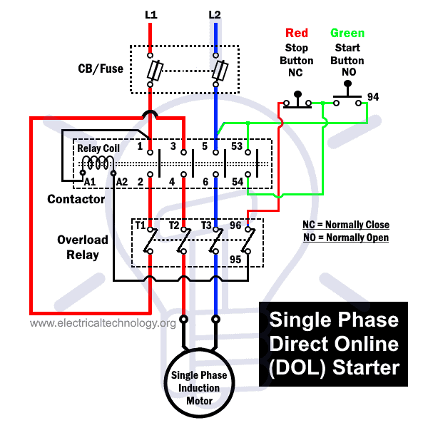
The wiring diagram for a DOL stater is shown below. A direct online starter consists of two buttons, a GREEN button for starting and a RED for stopping purpose of the motor. The DOL starter comprises an MCCB or circuit breaker, contactor and an overload relay for protection. These two buttons, i.e. Green and Red or start and stop buttons.
DOL Starter Working (Direct Online Starter) Principle,Control,wiring,power,diagram
DOL Starter (Direct Online Starter) is also knows as "across the line starter". DOL starter is a device consist of main contactor, protective devices and overload relay which is used for motor starting operations. It is used for low rating usually below 5HP motors. In direct online starter method of motor starting, the motor stator windings.
What are DOL and RDOL starters? Advantages, Disadvantages
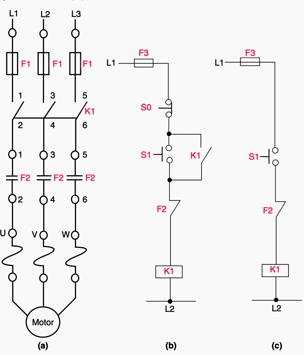
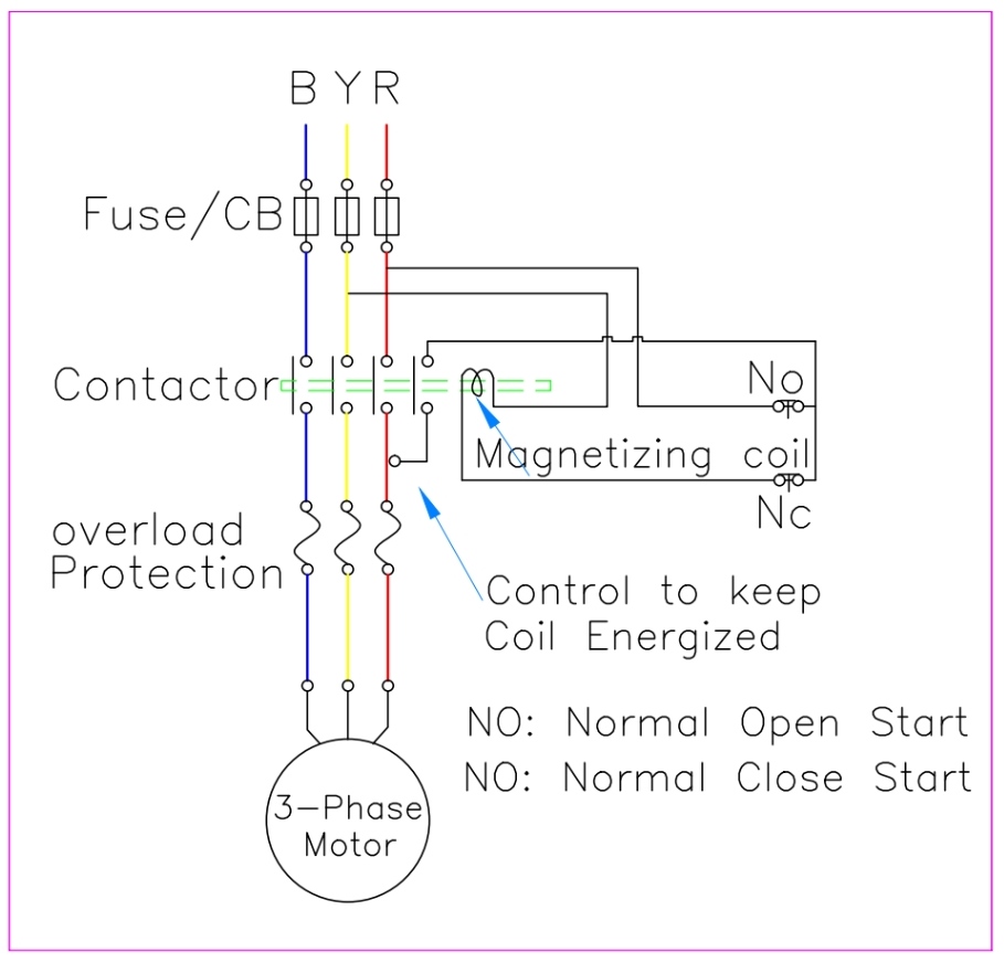
Fig. 1 (a) shows a typical direct on line starter called DOL starter suitable for a small squirrel cage induction motor consisting of a magnetic contactor and thermal overload relay and Fig. 1 (b) shows a schematic wiring diagram for its control circuit. When start push-button is pressed, the contactor coil is energised and its three normally.

Electrical Standards Direct Online (DOL) Starter
The DOl or Direct Online Starter also called across-line Starter is a method used for starting 3 Phase induction motor. In this starter technique, an induction motor is attached to the three-phase supply and the DOL starter provides the full line voltage to the motors connections. As this is a direct connection there is no damage for the motor.

Direct Online Starter (DOL Motor Starter) Circuit Diagram and Working Principle
The direct online starter is a basic and simple starter for starting the induction motor. In DOL Starter, we connect the stator winding of the induction motor directly to the three-phase supply voltage. Thus, the stator winding receives full line voltage. The DOL motor starter is suitable for starting small-rating motors because the motor draws.
DOL Starter Wiring Diagram (Direct Online Starter)
Wiring diagram Label 10. Links 11. Gasket 12. Grommet 13. Mounting Screw hole Fig. 1: DOL Starter. Raja+ Direct-on-line Starter (For Single Phase connection) Wiring Diagram for Single-Phase Motors Note: Connect 3/L2 to 2/T1 by 2cable of suitable size. (Max. 4mm) Hook on relay for
Dol Starter Control Circuit Diagram Explanation
Wiring Diagram of DOL Starter. Direct On Line Starter - Wiring Diagram. Working principle of DOL Starter. The main heart of DOL starter is Relay Coil. Normally it gets one phase constant from incoming supply Voltage (A1).when Coil gets second Phase relay coil energizes and Magnet of Contactor produce electromagnetic field and due to this.
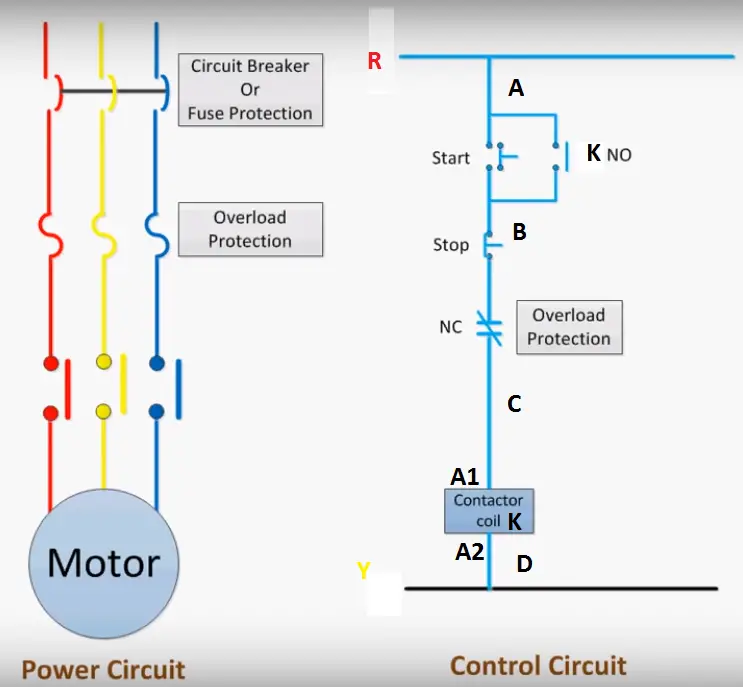
What is DOL Starter? Direct Online Starter Wiring and Working
DOL Starter Working. The 3 phase DOL starter wiring diagram is shown below. The DOL starter joints the 3 phase main wiring with the induction motor namely L1, l2 and L3 when the start switch is pressed. Generally, the Direct Online starter working can be done in two different stages namely DOL starter control circuit and DOL starter power circuit.
Explain Direct On Line (DOL) Starter With Diagram
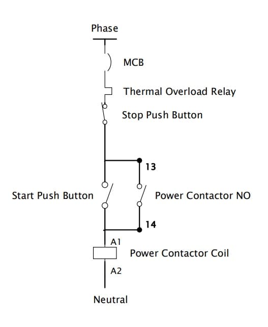
A DOL starter control diagram is a single-line diagram of the physical connections and layout of an electrical circuit, including the DOL starter's three primary components: the Contactor, Overload Relay, and Circuit Breaker. DOL Starter Control Diagram consists of components like the Main power contactor, start button, stop push button, and.
What is DOL Starter? Direct Online Starter Wiring and Working
DOL starter basic Diagram. Input section: it comes with one MCCB (Molded case circuit breaker) or MPCB (Motor protection circuit breaker) or MCB (Miniature circuit breaker) or SFU (Switch Fuse unit.).. The rating of the MCCB/MPCB should be higher than the motor rating. It is used to protect the motor under short circuit conditions.
DOL Starter Direct Online Starter Diagram, Construction, Advantages Electrical4u
This video is about the 3 phase dol starter control and main wiring animation with MCCB, magnetic contactor, thermal overload relay, NC NO switches, motor co.